Miniature SMA Step Attenuator
QEX September/October 2021 pp 9-21 by Tom Alldred VA7TA.
Return to Home Page
page last updated
12/19/2021
This page is for additional information about the QEX Step Attenuator
I have placed three orders for boards from JLCPCB for
the
QEX September/October 2021 “Miniature SMA Step Attenuator”
pp 9-21 by
Tom Alldred VA7TA. I had no idea of the popularity of this project.
The first batch,
of 10, was sold out very quickly.
All available boards from the second
order have been requested and reshipped.
Over 80 boards now have
been requested and the interest still continues.
NOTE:
As of 10/12/2021 I have placed
another (3rd) buy of 50 pieces.
Will continue to fill order
requests until
my inventory has been completely depleted.
[12/19/2021]
I inventory is 10 boards remaining
Contact me if
you are interested in a board
1 @ $3.00, 2 @ $4.50 ppd CONUS
Now have
info for international shipments
1@ $3.75 USD and 2@ $5.25 USD
Some additional information about the QEX article
BOM
Plus_60dBStepAtten_with Mouser.pdf
An ebay source for SMA connectors that include the
hardware
10X SMA female jack with nut connector end launch
PCB mount straight goldplated $5.80 + $1.50 shipping
Ebay - 10 SMA with hardware
If you have a need for 3 or more 1590A boxes
3 X New 1590A
Aluminum Metal Stomp Box Case
Enclosure Guitar Effect Pedal $10.99 + $4.50
shipping
Ebay - 3 1590A Boxes
Some Notes on my observations:
The original template in the QEX download
[SMA_StepAttenDrillTemplateRev1.jpg] is not at 1:1 scale.
It appears,
on my system, to be at approximately 1.535:1 so be careful !
Tom VA7TA sent me a pdf
of the cover at 1:1 scale.
Be sure to print at full size and check the
100mm lines.
StepAtnTemplate-Dwgs_User.pdf
Found
some minor dimensional discrepancies on the paper drill template above.
Perhaps I am just too fussy about accurate dimensions, but I created an
alternate template from openSCAD and the excel spreadsheet
noted in
the section below. Alt_Paper_Template.pdf
Do not forget to print at 1:1 scale
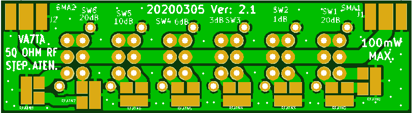
Also note for the cover and PCB that:
Spacing between J1 & SW1 center lines
is 10.5mm
Spacing between J2 & SW6 center lines is 9.5mm
Spacing between all SW center lines is 10mm
Spacing between J1 & J2
center lines is 70mm
Note the proper mounting locations of the SMA jacks and
the 6 switches.
Hole and position information from my excel file for the
top cover
drill
pos n Top Cover hole locations.pdf
The whole excel file:
drill pos.xlsx [I needed this for the 3D
template design]
Construction NOTE:
On page 5 of the article Tom mentions in
the second column
to mount the SMA connectors to the top cover before soldering to
the PCB.
Please observe this advice as assembly will be much
easier !
I am planning to make a 3D printed pilot hole template for
the cover,
along with a modification to the 3D printed 1590A cover mentioned
at
https://www.thingiverse.com/thing:2801379
Decided that I preferred my design for the box & Drill Template.
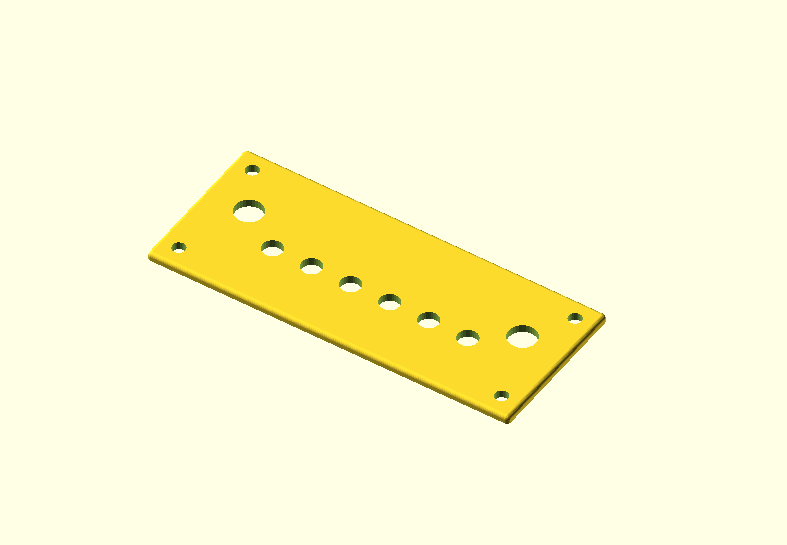
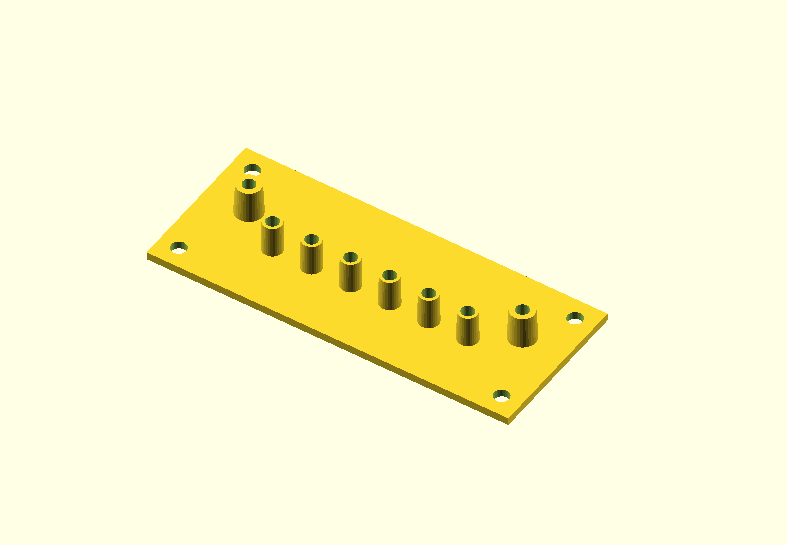
3D Printed Cover
Drill Template
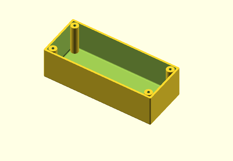
The 3D-Box if you want to see it
Atten_Box.png [uses #4 or M3 pan head
screws]
The Drill Template uses 1/8 " drill and is mounted on top of the metal 1590A
cover with
4, 6-32 machine screws inserted from the bottom side of the 1590A
cover and secured with nuts.
After the bigger holes have been drilled place the
template on the 1590A cover from the bottom
to check spacing, before final
assembly.
There is also a second template with 1/16" holes and no posts.
Design is verified [10/10/21]. Files posted below
QEX
Step Attenuator.zip.
Note,
haven't drilled the metal cover yet, but the template and the board fits in the
3D-cover.
contact info ok on QRZ
![]()